• Rss

SIL3 Pty Ltd

  • About SIL3 Pty Ltd
  • Contact Us
  • Consulting
    • Showcase
    • Safety Design Consulting
    • Embedded Firmware for Safety Applications
    • CPLD and FPGA Design
    • Printed Circuit Board Design
  • Technology
    • EWP Crush Protection
    • maxLMS
    • microLMS
    • LMS2
  • Safety Blog

Safety Blog

You are here: Home » Safety Blog » SafeTool » SafeTool – FMEDA Configuration

SafeTool – FMEDA Configuration

09 Aug 2015 / 0 Comments / in SafeTool/by Lachlan

To setup the FMEDA process in SafeTool a few elements must be manually entered:

  • The Altium Designer PCB Project
  • The type of hardware architecture:
    • Type A: Components with well known failure modes
    • Type B: Complex components / silicon
  • The number of channels in the system
  • A justification for each choice
  • The Demand Mode

safetool_fmeda_architecture

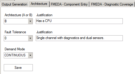
The information entered into SafeTool is used at the final step in determining the SIL level for the current design.

Recent Posts

  • FMEDA Process – Component Entry
  • FMEDA Process – Schematic Capture
  • SafeTool – FMEDA Configuration
  • SafeTool – FMEDA Component Entry
  • SafeTool – FMEDA Diagnostic Coverage

Archives

  • August 2015

Categories

  • SafeTool
← SafeTool – FMEDA Component Entry (previous entry)
(next entry) FMEDA Process – Schematic Capture →

© Copyright - SIL3 Pty Ltd - Terms and Conditions - Replete e-Commerce Theme by Kriesi
  • About SIL3 Pty Ltd
  • Contact Us
  • Consulting
  • Technology
  • Safety Blog