FMEDA Process – Schematic Capture
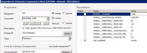
Each hardware component that we use on a PCB, not only has a Parts Database entry but also has a schematic symbol in Altium Designer. Within the symbol we have added links to enable the rapid creation of the necessary data for the FMEDA process.
Schematic Symbols
Each symbol contains additional information for the SafeTool application. This information includes:
- The channel (for multi channel MooN architectures)
- The function of the component in the system
- Its operating conditions when used in the system, including min, max and typical values.
This process allows the designer and design review team to quickly identify each component in the system, its function and its operating conditions.
Do you need help with your FMEDA process? Contact Us


